Multi-WAN Failover & Policy-Based Routing in UniFi
Contents
Enterprise network continuity requires eliminating single points of failure at the perimeter. Relying on a single primary broadband connection—such as a fiber optic line—leaves operational infrastructure vulnerable to Internet Service Provider (ISP) outages or physical cable damage. By deploying a secondary WAN connection, such as a 5G/LTE cellular modem or a secondary broadband provider, on a Ubiquiti UniFi Gateway (e.g., UDM-Pro, UXG-Pro, EFG, or UCG-Ultra), seamless failover and intelligent traffic distribution can be achieved.
1. Multi-WAN Operating Modes: Failover vs. Load Balancing
The UniFi Network Application supports two distinct multi-WAN operational modes, each serving specific architectural requirements:
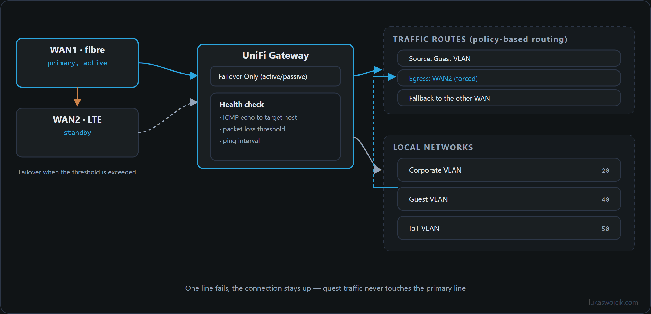
- Failover Only (Active/Passive): All outbound traffic is routed exclusively through the primary WAN interface (WAN1). The secondary interface (WAN2) remains on standby and activates only when packet loss or latency thresholds indicate a failure on WAN1. This mode is critical when WAN2 relies on a metered 5G/LTE cellular connection.
- Distributed Load Balancing (Active/Active): Outbound traffic is distributed across both WAN interfaces based on custom percentage weights (e.g., 80% / 20%). This maximizes total available throughput when utilizing two unmetered broadband connections.
2. Step-by-Step Configuration of Multi-WAN Failover
To configure automated failover on a UniFi Gateway, the following sequence must be executed within the UniFi Network Controller:
- Port Assignment & Interface Mapping: Navigate to
Settings > Internet. Select the primary broadband line asWAN1 (Primary)and map the secondary modem or SFP+/RJ45 port asWAN2 (Secondary). - Operational Mode Selection: Under the
WAN2configuration panel, set the Load Balancing mode toFailover Only. - Target Verification & Echo Server Setup: UniFi monitors WAN health by continuously sending ICMP echo requests. By default, ping targets point to
ping.ubnt.com. To improve detection accuracy, custom reliable DNS endpoints should be specified underSettings > Internet > WAN1 > Advancedby setting the Echo Server to custom IPv4 addresses (e.g.,1.1.1.1and8.8.8.8). - Failover Threshold Tuning: Adjust the packet loss threshold and ping interval to ensure rapid failover without triggering false positives during minor latency spikes.
3. Policy-Based Routing (Traffic Routes)
While automated failover protects against total outages, Policy-Based Routing (PBR) allows specific local subnets, VLANs, or applications to be directed through a designated WAN interface during normal operation. For example, high-bandwidth guest networks or automated offsite cloud backups can be forced over a secondary DSL line, reserving fiber bandwidth exclusively for voice-over-IP (VoIP) and enterprise services.
Step-by-Step Policy-Based Routing Setup
- Access Routing Policies: Navigate to
Settings > Routing > Traffic Routesand selectCreate Entry. - Define Route Name and Category: Assign a descriptive identifier (e.g.,
Route_Guest_VLAN_to_WAN2) and select the matching category (e.g.,All Traffic,Domain Name, orIP Address). - Specify Target Source: Choose the originating local network, VLAN, or specific host IP address group (e.g.,
VLAN 30 - Guest Network). - Assign Egress Interface: Select the desired WAN interface (e.g.,
WAN2) as the mandatory exit path. - Configure Failover Behavior: Check the
Fallback to alternative WANoption if traffic should revert to the primary interface when the assigned WAN port goes offline.
4. Summary & Architectural Value
What this tutorial achieves: The successful deployment of a fully automated, redundant dual-WAN edge infrastructure with customized ICMP health verification and explicit Policy-Based Routing rules for granular traffic segmentation.
Resulting value: Enterprise operations and home office environments gain zero-downtime internet connectivity. Outages on the primary fiber line trigger automated failover within seconds without requiring manual intervention or physical cable switching. Furthermore, policy-based routing prevents bandwidth congestion on critical production subnets and protects metered cellular backup links from unauthorized bulk data consumption.
Sources
Related articles