

UniFi Zone Matrix: Policy States for Server, CCTV and IoT Networks

Managing firewall rules using traditional LAN IN / LAN OUT lists can be a nightmare, especially when a network grows to include IoT devices, cameras, and private servers. Ubiquiti has revolutionized this process in their UniFi ecosystem with the Zone Matrix, a visual representation of the firewall policies.
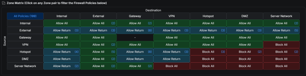
As the referenced screenshot shows, the Zone Matrix provides a grid where the Y-axis represents the Source (where the traffic originates) and the X-axis represents the Destination (where the traffic is going).
Understanding the Policy States
The matrix uses color-coded blocks to define routing behavior:
- Allow All (Green): The Source can freely initiate connections to the Destination.
- Allow Return (Blue): The Source cannot initiate new connections to the Destination. It can only send data back if the Destination initiated the connection first (stateful inspection).
- Block All (Red): Absolute isolation. No traffic can pass from Source to Destination.
Scenario 1: Securing a Server Network
A common security best practice is allowing internal trusted devices to access a local server (like a NAS or Home Assistant), while preventing that server from actively scanning or connecting to private devices if it gets compromised.
The screenshot at the top of this post shows exactly how:
- Set the policy from Source: Internal to Destination: Server Network as Allow All (Green). This lets the laptop access the server.
- Set the policy from Source: Server Network to Destination: Internal as Allow Return (Blue). This configuration ensures the server can reply to the laptop’s requests but is physically incapable of initiating a new connection to the internal network.
Scenario 2: Isolating CCTV and Smart Home (IoT)
Smart home devices and IP cameras are notoriously vulnerable to hacking. They should never have free access to the main trusted network. The Zone Matrix makes a “bulletproof” IoT isolation possible:
- Assign the cameras and smart home devices to a dedicated VLAN and map it to a specific Zone (the DMZ or Hotspot zone works, as does a custom “IoT” zone).
- Set Source: Internal to Destination: IoT Zone as Allow All. This allows a smartphone on the main Wi-Fi to view camera feeds or control smart lights locally.
- Set Source: IoT Zone to Destination: Internal as Allow Return (or Block All if no local control is needed and everything goes through the cloud).
- To prevent cameras from accessing the internet, set Source: IoT Zone to Destination: External as Block All.
Sources
Related articles

2 comments
colour-coding the intent rather than the packet flow is what makes this readable six months later — the old rule lists always needed a mental replay of the rotuing chain.
One case I cannot place in the matrix: remote access. Do VPN clients inherit the internal zone, or do they arrive as something of their own?
Something of their own. The VPN network is a network like any other and gets assigned to a zone; it does not inherit anything from the internal one, and expecting it to is the most common surprise when the matrix is introduced.
That is worth treating as a feature rather than an inconvenience. Remote access in its own zone can be granted exactly what it needs — the home automation interface on one port, the NAS on another — while the rest of the internal network stays out of reach for a device that is, by definition, somewhere else and possibly not fully trusted.
Two cells then deserve a deliberate answer instead of a default. VPN to Internal is the one that carries the actual access, so it belongs narrowed to hosts and ports. And Internal to VPN is usually not needed at all: a laptop at home rarely has to open a connection into a remote client, and leaving that cell open is a quiet way of undoing the separation the setup just created.