English
 Deutsch
 Polski
UniFi Zone Matrix: Policy States for Server, CCTV and IoT Networks

Contents
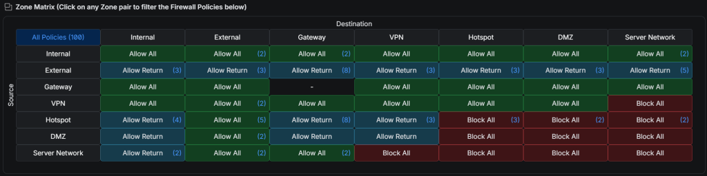
The UniFi Zone Matrix summarizes firewall policies between network zones. A zone groups interfaces or networks; a policy controls which traffic may pass. The matrix makes relationships easier to inspect, but a green or red cell is not a substitute for checking the actual rule list.
Read source and destination separately
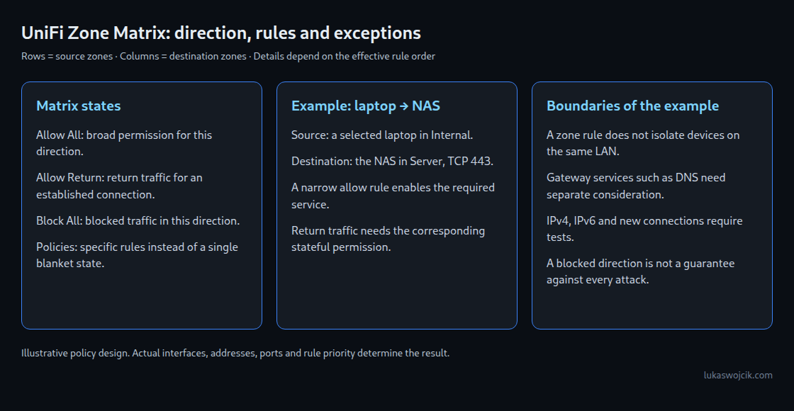
Rows show the source and columns the destination. Internal → Server Network therefore describes traffic leaving Internal for the server zone. The reverse cell is a separate direction. These are filtering policies, not a routing table or physical separation.
- Allow All: permits traffic for the zone pair represented by that cell.
- Allow Return: describes a setup allowing replies to permitted connections without generally allowing new connections in the reverse direction. The effective return-traffic policy must be checked.
- Block All: blocks the covered direction. An existing higher-priority exception can change the effective result.
- Policies: several specific allow/block policies apply; inspecting that list is essential.
Example: access to a server
A laptop needs an HTTPS connection to a NAS. A narrow allow rule from the laptop network to the NAS address and TCP port 443 expresses this need more precisely than allowing every service on every server. Return traffic must be permitted, for example through the corresponding automatic return rule.
A new connection initiated by the NAS toward the laptop should remain blocked unless a separate service requires that direction. This limits one attack path; a compromised server can still send harmful content through an allowed session. Host updates and application access controls remain necessary.
Example: cameras and IoT
A dedicated IoT VLAN assigned to a custom zone makes the intended boundary explicit. DMZ and Hotspot have different default purposes and policies, so those names are not interchangeable presets for a camera network.
Only the controller or recorder addresses and required ports need access. Camera-initiated events, DNS and time synchronization may need separate rules. Blocking IoT → External can stop direct internet access through that gateway, but also prevents cloud functions and updates. Traffic to the gateway itself needs separate consideration.
Two cameras on the same local network may communicate directly without crossing the gateway firewall. Zone policies alone therefore do not provide client isolation inside that network. Separate switch or wireless isolation controls may be needed.
Verify the intended boundary
A practical check covers four cases: a permitted connection succeeds; its reply arrives; a prohibited new reverse connection fails; and a prohibited external connection fails. Both IPv4 and IPv6 matter when enabled. Tests need actual application ports, not just ping. The effective rule order and logs help explain unexpected results.
Questions and answers
Are VPN clients automatically trusted Internal devices?
No. UniFi has a VPN zone for remote-user and site-to-site VPN traffic, while external VPN-client connections have a different role. The actual interface assignment and required access need inspection before rules are added.
Can a single device receive an exception?
A policy can narrow access to a particular device or address without moving the entire network. Address-based rules require stable addressing, but a DHCP reservation alone is not authentication and does not prevent address spoofing.
Does Block All prove complete isolation?
No. The relevant traffic must traverse the enforcing gateway and match the intended rules. Other interfaces, same-network traffic, explicit exceptions and application-level access are separate paths to assess.
Related articles