English
 Deutsch
 Polski
Linear Phase and Minimum Phase EQ: Comparing Delay, Pre-Ringing and Attenuation

Management Summary
An equaliser adjusts the balance of low and high sounds in a recording. Its processing method can also change timing: linear phase delays all frequency components equally, but may introduce small oscillations before a sharp drum hit. This can matter when mixing processed and original sound or monitoring live. The measured examples show a trade-off between delay, the intended tonal change and this early ringing. No method is automatically best; the recording and intended use determine the useful choice.
Contents
- How the measurement works
- Impulse response: ringing before and after the main impulse
- More delay: a deeper cut and longer pre-ringing
- Why the original target description misses the cut
- Synthetic kick: pre-onset level about 19 dB below the peak
- What this means for choosing an EQ
- Scope and limitations
- Questions and answers
- Sources
Fruity Parametric EQ 2 offers a linear phase mode. This delays frequency components by the same amount of time. One possible drawback is ringing before the delayed main impulse, especially around short attacks. This is called pre-ringing. Whether it is audibly distracting depends on the filter and the audio.
This comparison uses a biquad, a simple recursive digital filter, and two FIR filters with linear and minimum phase. FIR means that the impulse response has a finite duration. All versions receive the same target curve, but the cuts actually achieved differ. The experiment therefore does not isolate phase alone.
An impulse is a test signal with one non-zero sample. The impulse response is what the filter produces from that brief input. It reveals how long the filter’s effect continues and where the largest peak occurs.
How the measurement works
- The target is a 12 dB cut at 200 Hz. The dimensionless quality factor Q = 4 describes a relatively narrow band here. The starting filter is FFmpeg
equalizer=f=200:t=q:w=4:g=-12. Its frequency response is sampled at 60 logarithmically spaced frequencies from 20 Hz to 20 kHz and passed tofirequalizeras the target. - The versions are the biquad, linear phase FIR filters with
delayfrom 5 to 200 ms, and a minimum phase FIR filter. This parameter specifies filter delay, not the full duration of the impulse response. The setup uses FFmpeg 7.1.5, a 44.1 kHz sample rate and floating-point WAV files on a Raspberry Pi 4. The settingaccuracy=5stays constant. - A single input impulse occurs at 0.5 s. The movement of the largest output peak gives the time offset in the table. This measures the saved signal; it is not a complete real-time latency measurement of a DAW and its audio buffers.
- Ringing is measured after subtracting the suitably delayed input impulse from the output. This difference signal describes the waveform change. Squaring multiplies each value by itself, so positive and negative excursions both count without cancelling. Its first and last values above −60 dB relative to its largest absolute value define the reported duration. The energy share before the main impulse is the sum of squared difference values before that point divided by the sum over the entire difference signal. It is neither extra physical energy nor a share of total output energy.
- A synthetic kick also passes through the same versions. The pre-onset level is the largest absolute sample value within 20 ms before the time-aligned onset, relative to that version’s output peak. The lead begins at the first actual sample above −60 dB relative to that peak. The original analysis used a maximum window extending 1 ms in each direction. That made the start appear about 0.98 ms too early and has been corrected.
Impulse response: ringing before and after the main impulse
| Version | Main-peak offset | Pre-ringing | Post-ringing | Difference energy before | Level at 200 Hz |
|---|---|---|---|---|---|
| Biquad | 0.000 ms | 0.00 ms | 21.09 ms | 0.00 % | −12.00 dB |
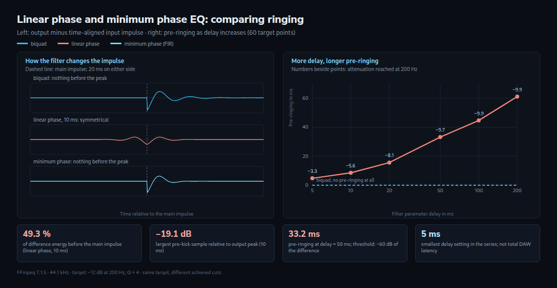
| linear phase, delay 10 ms | 10.000 ms | 8.57 ms | 8.57 ms | 49.28 % | −5.59 dB |
| linear phase, delay 50 ms | 50.000 ms | 33.24 ms | 33.24 ms | 49.43 % | −9.70 dB |
| minimum phase (FIR) | 0.000 ms | 0.00 ms | 11.97 ms | 0.00 % | −5.59 dB |
The biquad’s difference signal extends 21.09 ms after the impulse; the minimum phase FIR extends 11.97 ms. Neither has a pre-impulse component above the measurement threshold. The linear phase versions ring symmetrically around the delayed main impulse. About 49.3% of the difference energy lies before it, with a small portion at the midpoint itself. The cuts also differ, so this is not a comparison at identical frequency responses.
More delay: a deeper cut and longer pre-ringing
| Filter parameter delay | Level at 200 Hz | Pre-ringing | Difference energy before |
|---|---|---|---|
| 5 ms | -3.27 dB | 4.78 ms | 49.00 % |
| 10 ms | -5.59 dB | 8.57 ms | 49.28 % |
| 20 ms | -8.10 dB | 15.65 ms | 49.39 % |
| 50 ms | -9.70 dB | 33.24 ms | 49.43 % |
| 100 ms | -9.86 dB | 44.76 ms | 49.43 % |
| 200 ms | -9.86 dB | 61.22 ms | 49.44 % |
In this series, increasing delay brings the cut closer to the target. A 5 ms setting reaches only 3.27 dB of the requested 12 dB, while 50 ms reaches 9.70 dB. Pre-ringing also extends further. The roughly 49% still refers only to the difference signal in these tests; it is not a general energy share for music.
Why the original target description misses the cut
With 60 points, even 200 ms reaches only −9.86 dB instead of −12 dB. A wider band with Q = 1 reaches −11.78 dB at just 50 ms. For the narrow band, the shortfall is 2.30 dB at 50 ms and about 2.14 dB at 100 and 200 ms. It therefore does not stay identical at every delay.
An additional check shows the effect of point placement. The original grid jumps from 185 to 208 Hz without a point at 200 Hz. Adding that point improves the 200 ms result from about −9.86 to −11.69 dB. Using 84 points, packed more closely around the narrow band, reaches −11.82 dB. This check stores point levels with six decimal places rather than two. The original attempts with 150 and 377 points fail, but that does not establish a universal 100-point limit or insufficient RAM. Delay, point placement and filter design jointly affect accuracy.
Synthetic kick: pre-onset level about 19 dB below the peak
| Version | Largest absolute sample in preceding 20 ms, relative to peak | Corrected lead above −60 dB | Sample peak |
|---|---|---|---|
| without EQ | no signal | 0.00 ms | −1.05 dBFS |
| Biquad | no signal | 0.00 ms | −2.77 dBFS |
| minimum phase (FIR) | −135.89 dB | 0.00 ms | −2.58 dBFS |
| linear phase, delay 10 ms | −19.12 dB | 6.96 ms | −2.19 dBFS |
| linear phase, delay 50 ms | −19.25 dB | 13.90 ms | −2.01 dBFS |
In the linear phase versions, the largest value before the aligned onset is about 19 dB below the respective output peak. The corrected analysis gives leads of 6.96 and 13.90 ms. This establishes pre-ringing in the signal, but not an audible pre-echo; that would require a listening comparison. The very small values from the minimum phase version are far below the −60 dB threshold.
What this means for choosing an EQ
Linear phase can help when processed and unprocessed paths are combined and extra frequency-dependent phase shifts are unwanted. Correct timing alignment is essential. For sharp attacks or live monitoring, a low-delay mode may be more suitable. This one measurement does not establish a universal ranking for mastering, bass or multi-microphone recordings. A useful comparison requires frequency responses as similar as possible, followed by listening.
An additional 50 ms of filter delay applies independently of the audio buffer. The linked latency and buffer calculator puts such times in context; the FL Studio vocal-chain article discusses EQ placement in the signal path.
Scope and limitations
- The measured filters are from FFmpeg, not Fruity Parametric EQ 2. Its LIN context menu offers several Precision levels; the manual states that greater precision increases latency. These FFmpeg numbers are not measurements of those levels.
- In this setup, achieved attenuation depends on both the filter’s duration and the target-curve description. The original shortfall is not a fundamental limit of linear phase EQs. The additional check improves the target description; the other tables deliberately retain the original 60-point setup.
- The kick is a synthetic, short attack. Other recordings can produce different pre-ringing and audibility. A softer onset does not guarantee a particular reduction in decibels.
- Symmetry applies to the linear phase impulse responses examined here. Roughly 49% is not a fixed share for arbitrary cuts or boosts. No boost was measured, and its difference signal cannot generally be obtained simply by reversing the sign.
Questions and answers
Why does linear phase usually require extra delay?
A real-time system can respond only after receiving a signal. The linear phase filter used here rings before and after its main impulse. Its whole response is delayed so that no output is required before the input arrives. A minimum phase filter does not require this symmetric arrangement. That does not make every such plug-in latency-free: block processing or oversampling can add delay. The table’s 0.000 ms describes only the measured main-peak position.
DAW latency compensation aligns related signal paths, often by delaying the faster paths. Suitable playback or offline processing can also read material earlier. After alignment, pre-ringing lies before its associated main impulse. This does not allow an unknown live input to be anticipated.
Does more delay remove pre-ringing?
Not in this series: the duration above the chosen threshold increases from 4.78 to 61.22 ms. For the kick, the two tested settings remain near −19 dB relative to their respective peaks before onset. Other filters, windows and target curves can give different results.
What happens when the processed path is mixed with the original?
With a minimum phase EQ, extra frequency-dependent phase shifts can change the sum. A time-aligned linear phase EQ avoids those shifts in this setup. The mixed result still does not simply equal the EQ curve: adding an unchanged signal, for example, weakens the effect of a cut. Both the filter response and the levels of the two paths determine the combined response.
Without timing alignment, combining paths can create regularly spaced dips in the frequency response. As a simple example, two otherwise identical signals at equal levels and 10 ms apart cancel at 50, 150, 250 Hz and further odd multiples of 50 Hz. An EQ also changes amplitudes, so the actual dips are not necessarily complete or described exactly by that example. An impulse comparison can reveal the timing offset between paths.
Sources
- Image-Line: Fruity Parametric EQ 2: manufacturer information on Standard and LIN modes, Precision levels, latency and HQ options.
- FFmpeg 7.1.5: Filters Documentation: definitions of
delay,accuracy,gain_entryandmin_phase. Article values come from the reproduced measurement scripts and the additional check described above. - The tables contain sample peaks and difference-signal measurements, not LUFS or true-peak measurements. dBFS refers to digital full scale at 0 dBFS; negative values are below that reference.
Related articles